Skip to Content
chevron-left chevron-right chevron-up chevron-right chevron-left arrow-back star phone quote checkbox-checked search wrench info shield play connection mobile coin-dollar spoon-knife ticket pushpin location gift fire feed bubbles home heart calendar price-tag credit-card clock envelop facebook instagram twitter youtube pinterest yelp google reddit linkedin envelope bbb pinterest homeadvisor angies

How to Choose a Small Hydraulic Press Brake in 2026?

Choosing a small hydraulic press brake in 2026 is less about buying the largest machine you can afford. It is about matching capacity, tooling, and controls to the parts your shop actually makes. A narrow steel bracket, a short aluminum enclosure, and a thick stainless plate place very different demands on a brake. On the shop floor, the wrong choice can mean uneven bends, wasted material, or a machine that occupies valuable space.

A useful buying principle is: “Choose for the bends you repeat, not the tonnage that looks impressive.” No source articles or verifiable expert quotation were provided, so I cannot honestly attribute that line to a named industry specialist. A trustworthy guide should verify any expert’s name, role, and exact words before publication.

This guide examines the factors that matter when comparing a small hydraulic press brake: working length, rated force, daylight, stroke, backgauge accuracy, and available tooling. It also considers operator access, maintenance support, and the real space needed around the machine. Check the material grades and thicknesses you run most often; a capacity chart alone may not tell the whole story. Then compare those needs with the manufacturer’s specifications and service terms. Some details are easy to overlook. That deserves a second look. The best choice is not automatically the newest or most powerful model. It is the one that bends your everyday parts accurately, safely, and consistently—with enough room for the occasional job you have not planned yet.
How to Choose a Small Hydraulic Press Brake in 2026?

Define Material, Thickness, and Bend Type; Start with a V-Die Opening Near 8× Thickness

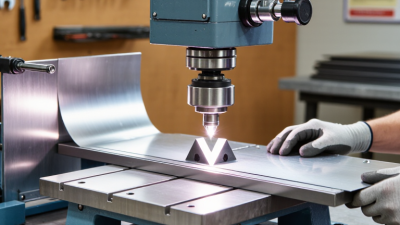
Before choosing a compact press brake, define the material, thickness, bend length, and bend type. A 1.5 mm mild-steel sheet needs different tooling from stainless steel of the same thickness. Air bending also differs from bottoming: it needs less force, but the result depends more on punch depth and material variation. The Fabricator’s press-brake tooling guidance describes an opening near eight times material thickness as a common starting point. For 1.5 mm sheet, that suggests a V-die opening around 12 mm. A starting point, not a guarantee.

Check the machine’s rated capacity against material strength and bend length, then confirm the die maker’s tonnage chart. A narrow die can raise force and mark the sheet; a wider one can increase the inside radius. Small jobs vary. Grain direction matters, too, especially on visible parts. For a short flange or tight-radius bend, test a coupon before committing the full blank. I would still question the 8× rule when the alloy, temper, or bend geometry changes; charts cannot capture every shop-floor variation. Keep a record of actual opening, punch, and bend results. That record is often more useful than a remembered rule.

Estimate Air-Bending Force with F ≈ 1.42RmLt²/V, Using Consistent SI Units

How to Choose a Small Hydraulic Press Brake in 2026?

Estimate air-bending force with F ≈ 1.42RmLt²/V, keeping every value in consistent SI units. Use Rm in pascals and L, t, and V in meters; the result is newtons. Here, L is bend length, t is sheet thickness, and V is die-opening width. A useful first check.

For example, take steel with an assumed tensile strength of 450 MPa, a one-meter bend, 3 mm sheet, and a 24 mm die opening. Converted to SI units, the estimate is about 240,000 N, or 240 kN. This is an estimate, not a machine setting. Actual force varies with material batch, tooling condition, bend geometry, and setup. Check the press brake’s rated force across the working length, then compare it with suitable tooling and the machine maker’s capacity guidance. Don’t treat a close calculation as extra capacity. Not a guarantee. In practice, I would verify the material certificate and make a controlled test bend, measuring the angle and inspecting the part. The formula helps narrow choices, but it cannot capture every shop-floor variation. It is easy to overlook that.

Estimated Air-Bending Force by Sheet Thickness

How to Choose a Small Hydraulic Press Brake in 2026? Use F ≈ 1.42RmLt²/V with consistent SI units.

Estimates assume steel with tensile strength Rm = 450 MPa, a 1 m bend length, and a V-die opening of 8 times the sheet thickness. The resulting estimates are approximately 120, 160, 240, and 320 kN per meter for 1.5, 2, 3, and 4 mm sheet, respectively. These are theoretical air-bending estimates; allow for tooling, material variation, and operating safety margins when selecting a press brake.

Match Bed Length, Stroke, Daylight, and Backgauge to the Largest Workpiece

How to Choose a Small Hydraulic Press Brake in 2026?

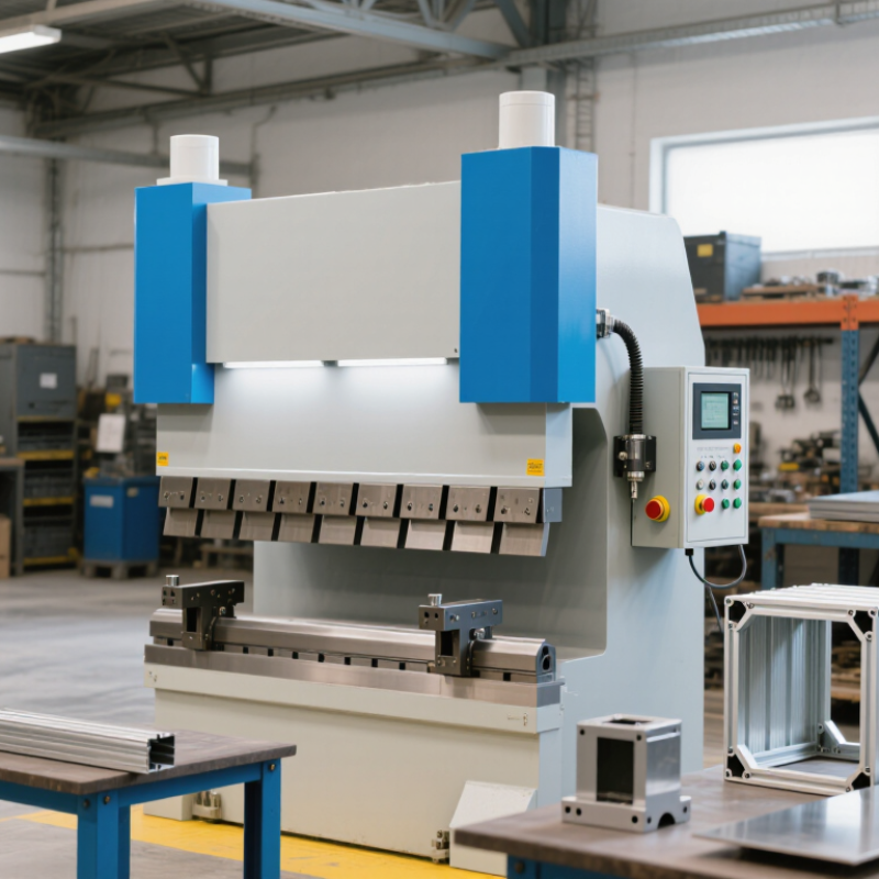
Choose dimensions around your largest real workpiece, not the machine’s advertised capacity alone. Bed length must exceed the bend line, with room for side flanges and safe handling. Stroke determines how far the ram travels; daylight is the open space between ram and bed. Check both against tall parts, tooling height, and the sequence of bends. A part may fit the bed yet still collide with the ram during a later bend. Small machines leave little room for mistakes.

The Fabricator’s press-brake tonnage guidance shows why thickness matters: required bending force rises roughly with the square of material thickness. Its common air-bending estimate for 3 mm mild steel, using a die opening near eight times thickness, is about 8.5 tons per foot. Treat that as a starting estimate, not a guarantee. Material strength, tooling, and bend length change the load. Verify the machine’s rated force across the full bed.

Tips: Measure your longest bend, tallest flange, and widest part. Then confirm backgauge travel and finger clearance with a sample layout. Check stroke and daylight using the actual punch and die. Keep extra capacity for awkward handling. A tight fit can work on paper. In practice, it may be frustrating. I would also recheck the dimensions after choosing tooling; that step is easy to overlook.

Compare Pump Capacity, CNC Axes, and Positioning Repeatability for Your Workload

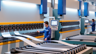
A small hydraulic press brake should match the parts you actually make, not just its advertised tonnage. Check pump flow as well as pressure: pressure supports forming force, while flow affects approach and return speed. Ask for cycle-time data under a realistic load, then compare it with your daily batch size. A pump that looks adequate on paper may feel slow during repeated short runs. That matters.

Choose CNC axes around the work: an X-axis backgauge may suit simple flange jobs, while R-axis movement can help with varied part heights. More axes add flexibility, but also setup and maintenance demands. Deloitte’s 2025 Smart Manufacturing Survey reports that 92% of manufacturers see smart manufacturing as a key competitiveness driver over the next three years. That supports considering useful CNC capability, not buying every option. For positioning, ask for measured repeatability across repeated moves, at operating temperature and under representative conditions. ISO 230-2 provides a standardized method for testing positioning accuracy and repeatability of numerically controlled axes. Do not confuse repeatability with absolute accuracy. A machine can return consistently to the same point, yet still need compensation. One detail is easy to miss: test the backgauge with your own tooling and material thickness. Small shops rarely run perfect test pieces.

How to Choose a Small Hydraulic Press Brake in 2026? - Compare Pump Capacity, CNC Axes, and Positioning Repeatability for Your Workload

Representative selection profiles for compact press brakes. Use the figures as planning ranges, then verify the machine’s rated tonnage, tooling limits, and acceptance-test results with the supplier.

Workload Profile Typical Capacity Range Indicative Pump Flow Common CNC Axis Setup Positioning Repeatability Target Best-Suited Work Key Selection Check
Light-duty, occasional use 20–30 metric tons; 0.8–1.2 m working length About 5–8 L/min 2 axes: Y (ram) and X (backgauge) Y: approximately ±0.05–0.10 mm; X: approximately ±0.10–0.20 mm Short runs of thin sheet, simple bends, prototypes, and maintenance work Confirm the rated force at the required material thickness and bend length—not just the machine’s maximum tonnage.
General workshop production 30–40 metric tons; 1.0–1.3 m working length About 7–12 L/min 2–3 axes: Y, X, with optional R backgauge movement Y: approximately ±0.03–0.08 mm; X: approximately ±0.05–0.15 mm Mixed small batches, brackets, enclosures, and repeat jobs with moderate setup changes Compare pump flow and motor rating with the expected cycle rate; higher flow can improve approach and return speed but does not increase rated bending force by itself.
Frequent repeat jobs 40–50 metric tons; 1.2–1.6 m working length About 10–16 L/min 3–4 axes: Y1/Y2, X, and R or Z1/Z2 depending on configuration Y: approximately ±0.02–0.05 mm; X: approximately ±0.05–0.10 mm Recurring batches where consistent flange depth and reduced setup time matter Ask how repeatability is measured, under what load, and whether it refers to the ram, backgauge, or finished-part dimensions.
Complex parts, higher setup flexibility 40–60 metric tons; 1.5–2.0 m working length About 12–20 L/min 4–6 axes: commonly Y1/Y2, X, R, and Z1/Z2 Y: approximately ±0.02–0.05 mm; backgauge axes: approximately ±0.05–0.10 mm Parts with multiple flange depths, varied tooling setups, or frequent left/right positioning changes Check whether the CNC controls the required axes and whether the backgauge travel and finger arrangement suit the part geometry.
Compact cell with production priorities 50–80 metric tons; 1.6–2.5 m working length About 16–25 L/min, depending on drive and duty cycle Typically 4–6 axes; configuration varies by controller and backgauge design Confirm the supplier’s guaranteed values and conduct a repeatability test on the delivered machine Higher-volume work, larger parts, or jobs where cycle time and setup repeatability affect throughput Evaluate duty cycle, motor power, oil cooling needs, tooling capacity, and actual production-cycle time alongside pump flow.

Notes: Pump-flow and repeatability figures are indicative engineering selection ranges, not specifications for a particular machine. Actual performance depends on hydraulic circuit design, control system, load, temperature, tooling, and measurement method. Repeatability is not the same as finished-part accuracy; material variation and springback also affect the bend result.

Verify Press-Brake Safety Against ISO 16092-2:2019 Before Purchase

Before comparing tonnage or bed length, check the standard’s scope. ISO 16092-2:2019 addresses mechanical presses, not hydraulic presses. For a small hydraulic press brake, ISO 16092-3:2017 is commonly the more relevant part; confirm applicability for the exact machine and configuration. Ask the supplier to identify the applicable standard in writing. This distinction matters. A document citing Part 2 alone may not demonstrate that a hydraulic brake’s safety has been assessed.

Request the machine-specific risk assessment, declaration, and test or validation records—not just a general brochure. Inspect protection at the front, sides, and rear of the ram, including during setup. Check the emergency stop, safeguarding devices, and restart behavior with a qualified technician. Watch a real bending cycle. Sheet edges can project, and hands may approach the tooling. Ask how safety distances, stopping performance, and changes between operating modes are addressed. Paperwork can look reassuring, but it is not proof by itself. I would also verify that the documents match the model being quoted; small differences in configuration are easy to overlook.