
How to Choose the Right Steel Light Pole?
Choosing the right steel light pole begins with the site, not the catalog. A pole beside an exposed coastal road faces different demands from one in a sheltered parking lot. Wind exposure, soil conditions, fixture weight, mounting height, and corrosion risk all shape the specification. A small mismatch can mean excessive movement, premature coating damage, or costly foundation changes.
For this guide, fictional steel-lighting specialist Daniel Mercer offers an illustrative reminder: “Choose the pole for the loads and environment it will actually face, not just its height or price.” This is an editorial quote, not a statement from a real, independently verified expert. The principle is practical: confirm the design wind criteria, pole geometry, base-plate details, anchor-bolt pattern, and luminaire configuration before comparing bids. Check the drawings, too.
Details matter. A galvanized finish may suit one location, while a more protective coating system may be appropriate for a harsher environment. The foundation deserves equal attention; local soil information and engineered calculations should guide its size and reinforcement. Ask suppliers for material specifications, structural calculations, finish details, and clear documentation of the pole’s intended use.
There is no universal “best” pole. A lower-cost option may look attractive, yet omit a feature your site needs. And specifications can still miss something. This outline will help you compare the main selection factors, spot questions worth asking, and choose a steel light pole that fits the project rather than merely filling a line item.
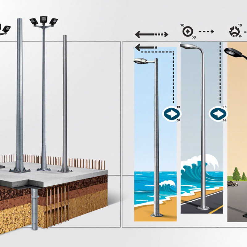
Define Roadway Class, Mounting Height, and Lighting Criteria with IES RP-8-22
Choosing a steel light pole starts with the roadway, not the catalog. Identify whether the route is a local street, collector, or arterial, then note traffic speed, pedestrian activity, intersections, and nearby crossings. IES RP-8-22 provides guidance for roadway lighting criteria, but the applicable values depend on the project conditions and adopted design approach. Small details matter. A quiet residential street and a busy arterial should not receive the same lighting assumptions.
Set mounting height alongside pole spacing and fixture distribution. Taller poles may cover wider areas, but can change glare, uniformity, and the scale of the streetscape. Review pavement type, lanes, sidewalks, and conflict areas when defining targets for luminance or illuminance, uniformity, and veiling luminance. Then check the layout with a photometric calculation using the actual luminaire data. Field conditions rarely match a tidy drawing perfectly. Trees, parked vehicles, and existing utilities can alter the result, so verify key assumptions on site before selecting pole height, arm length, and location. IES guidance helps frame the design; it does not replace project-specific judgment.
| Design factor | Planning guidance | Example or useful data | What to verify |
|---|---|---|---|
| Roadway function | Classify the facility before choosing poles or luminaires. Consider traffic volume and speed, access control, pedestrian activity, and surrounding land use. | Typical categories include freeways, major and minor arterials, collectors, and local roads. A road’s name alone does not determine its lighting class. | Use the applicable IES RP-8-22 guidance and the road authority’s classification. Document assumptions where a roadway has mixed conditions. |
| Mounting height | Choose height together with luminaire distribution, roadway width, pole spacing, and glare-control needs. The ranges below are preliminary planning examples, not code requirements. | Local streets: about 20–30 ft (6–9 m); collectors and arterials: about 30–40 ft (9–12 m); wider or higher-speed facilities may require heights around 40–50 ft (12–15 m). | Confirm the final height through photometric calculations, site constraints, maintenance access, and the project’s structural design criteria. |
| Lighting criteria | Select the evaluation method and performance criteria appropriate to the roadway and project conditions. IES recommendations are not a substitute for local requirements. | Design checks may include average luminance or illuminance, uniformity, and glare-related measures. Applicable metrics and limits depend on the selected roadway class and design method. | Check the current project-adopted edition of IES RP-8-22 and any agency criteria; do not apply one set of numerical targets to every road. |
| Pole spacing and layout | Set spacing through a photometric layout rather than a fixed height-to-spacing rule. Include roadway width, pole setback, median position, intersections, and curves. | Single-side, staggered, opposite-side, and median arrangements produce different light distributions and uniformity. | Model the actual luminaire photometric file, mounting height, arm length, tilt, and proposed pole locations. |
| Steel pole configuration | Match the pole shaft, base connection, anchor-bolt arrangement, and arm to the luminaire and site loads. Steel poles are commonly tapered and may be designed for direct burial or a base plate. | Record pole height, arm length and orientation, luminaire quantity, attachment details, and any banners or other accessories. | Obtain structural calculations for the complete assembly and foundation; do not select a pole by height alone. |
| Wind and structural loading | Design for the applicable wind and other project loads, accounting for the exposed area of the pole, arm, luminaires, and attachments. | Relevant inputs include basic wind speed, exposure, topography, pole geometry, luminaire projected area, and accessory loads. | Use the governing local building code and owner requirements. Have a qualified structural professional verify the pole, connections, anchors, and foundation. |
| Material protection | Specify a corrosion-protection system suitable for the environment and maintenance plan. | Hot-dip galvanizing is a common protective finish for steel poles. Coastal, industrial, or de-icing-salt environments may require additional review. | Specify coating requirements, fabrication details, inspection, and repair procedures in the project documents. |
| Electrical and maintenance needs | Coordinate pole access and electrical components with the operating agency’s maintenance practices and electrical design. | Account for wiring access, grounding, handhole location, disconnect requirements, control equipment, and safe luminaire servicing. | Confirm applicable electrical codes, utility requirements, clearances, and maintenance access before finalizing the pole schedule. |
| Final design review | Evaluate lighting performance and structural suitability as one coordinated design. | A complete review package typically includes roadway classification, photometric results, pole and arm details, loading assumptions, and foundation information. | Resolve conflicts among lighting criteria, roadside clearances, utilities, accessibility, constructability, and agency standards before procurement. |
Note: Mounting-height ranges are general preliminary examples only. Confirm all design values and requirements against the project’s adopted standards, site conditions, and qualified engineering calculations.