
5 Best Tokimec Equivalent Pumps for Global Buyers
Choosing a Tokimec Equivalent Pump is not a brand-name substitution exercise. It is a compatibility decision grounded in operating data. Buyers should compare displacement, rated pressure, flow, shaft dimensions, mounting, rotation, and port connections. A pump may appear identical on a catalog page yet behave differently under load. Small mismatches matter.
As a practical engineering principle puts it: “Equivalent does not mean identical; it means verified for the intended duty.” This is a selection guideline, not a quotation attributed to a named expert. No source-backed expert statement was provided, so assigning one to a person would be misleading. That distinction matters when reliability is part of the purchase.
The five options in this guide give global buyers a structured starting point. Each candidate should be checked against the original Tokimec pump’s model code and the machine’s real operating conditions. Confirm fluid type, temperature range, continuous or intermittent duty, and installation limits. Then request a datasheet and written confirmation from the supplier. A short checklist helps. So does a careful conversation with a qualified hydraulic technician. Supplier claims alone may not settle every question; independent verification is still wise. One overlooked detail can mean extra downtime, even when the replacement looks right.
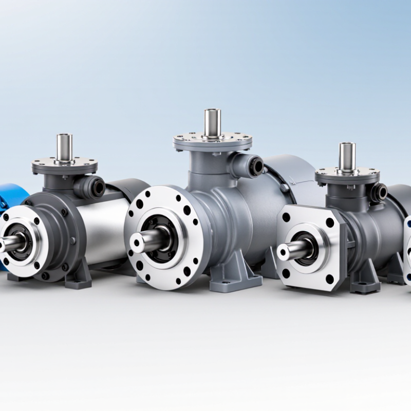
Tokimec Pump Fundamentals: Vane Design, Displacement, Flow, and Pressure
A vane pump moves oil as rotor-mounted vanes travel along a cam ring. The expanding chambers draw fluid in; shrinking chambers push it toward the outlet. Fixed-displacement models deliver a set volume per revolution, while variable-displacement designs adjust chamber volume. Small clearances matter. Oil temperature and contamination can increase leakage or wear, reducing delivered flow.
Flow is approximately displacement multiplied by rotational speed, then reduced by volumetric losses. For example, a 20 cm³/rev pump at 1,500 rpm produces 30 L/min theoretically. At 90% volumetric efficiency, actual flow is about 27 L/min.
This is an estimate, not a guarantee. ISO 4409:2019 specifies methods for measuring hydraulic pump performance, including flow, speed, and pressure. Compare test conditions before comparing catalog figures. A catalog number alone can mislead.
Pressure is created by resistance in the circuit, not by the pump independently “making” pressure. A relief valve limits excessive pressure and protects components. The U.S. Department of Energy’s Improving Pumping System Performance sourcebook reports potential energy savings of 20–50% through pumping-system optimization, depending on the installation. That figure covers system-level opportunities, not a promise of pump efficiency. Check inlet conditions, oil viscosity, duty cycle, and noise at the machine. Real installations are rarely perfect.
How to Match Equivalents Using cm³/rev, L/min, and Rated MPa
A Tokimec-equivalent pump should match the job, not just the old pump’s label. Start with displacement, measured in cm³/rev. This figure tells you how much fluid the pump moves per shaft revolution. Check the machine’s operating speed, too.
Check the required L/min at the pump’s normal working speed, then compare it with the candidate’s rated flow. A catalog maximum can be misleading. Next, compare rated pressure in MPa, and distinguish continuous pressure from short-duration peak pressure. A pump rated for a high peak may not tolerate that load all day.
Look closely at shaft rotation, mounting dimensions, port positions, and fluid requirements; small differences can turn a promising match into a costly installation problem. Ask for a performance curve when the catalog leaves gaps. It happens.
Record the machine’s real speed and pressure before ordering, and allow for operating conditions that are not perfectly steady.
Five Candidate Series: Yuken PV2R, Nachi VDC, Daikin V, Parker T6, Eaton V
Equivalent selection is not a catalog-name match; it is a duty-point check. The five candidate families span fixed-displacement double-vane pumps, compact fixed-displacement units, and variable-displacement vane designs. They differ in pressure response, mounting, shaft options, and noise behavior. The U.S. Department of Energy’s 2006 Improving Pumping System Performance sourcebook estimates that pumping systems use nearly 20% of global electricity. That figure covers pumping broadly, not hydraulic circuits alone, but it makes efficiency worth checking.
For a fair comparison, record flow, operating pressure, rotation, port layout, fluid viscosity, and peak temperature. Then check the actual duty point against each candidate’s pressure-flow curve, not just its maximum rating. The DOE’s 2014 motor-systems sourcebook attributes about 68% of U.S. manufacturing electricity use to motor-driven systems, reinforcing the value of measuring the complete power unit under load. Small details matter. A cold-start test may look fine, while a warm machine reveals leakage or noise. The comparison is imperfect without matched test conditions; even a familiar mounting footprint cannot guarantee an easy installation. Check shaft engagement and relief settings before ordering.
Installation Checks: ISO 4401 Mounting Interfaces and Shaft Dimensions
When comparing equivalent pumps, check the mounting interface before ordering. ISO 4401:2005 provides dimensional tables for hydraulic valve mounting surfaces, including size families such as 03, 05, and 07. It does not specify pump shaft dimensions. That distinction is easy to miss.
Measure the port pattern and bolt centers against the equipment drawing, not a catalog photo. Confirm port locations, sealing-face condition, and any locating recess with a caliper or depth gauge. A few millimeters can prevent a flush fit. Small errors matter. For pump flange and shaft-end details, ISO 3019-2:2001 is a relevant metric reference; the exact shaft diameter and key or spline form still depend on the pump configuration. Record the existing shaft extension, diameter, keyway width, and coupling engagement depth before selecting a substitute.
Keep the measurements with the maintenance record. Include the interface size, drawing revision, units, and measured values. Then compare them with the replacement supplier’s certified dimensional drawing. I have seen teams check the bolt pattern but overlook the pilot recess; the pump bolts down, yet the coupling sits out of line. That is not a glamorous failure, but it can create vibration and wear. Standards narrow the search. They do not replace a physical fit check.
5 Best Tokimec Equivalent Pumps for Global Buyers - Installation Checks: ISO 4401 Mounting Interfaces and Shaft Dimensions
Selection guide: ISO 4401 specifies mounting interfaces for hydraulic control valves, not pump mounting flanges or pump shaft dimensions. Confirm pump mounting and shaft details against the specific pump drawing before ordering.
| Pump type to consider | Typical use | ISO 4401 interface check | Pump mounting check | Shaft dimensions to verify | Buyer action |
|---|---|---|---|---|---|
| Axial-piston, variable displacement | Applications requiring adjustable flow and pressure compensation or other control options. | Match any valve or manifold mounted on the pump assembly to its stated ISO 4401 size and port pattern. The pump porting itself is not defined by ISO 4401. | Confirm flange style, pilot diameter, bolt pattern, and port positions from the pump drawing. | Record shaft-end type, major diameter, usable length, and key or spline details; these are model-specific. | Compare displacement, pressure rating, control arrangement, rotation, and the complete mounting drawing. |
| Axial-piston, fixed displacement | Systems needing a fixed displacement per revolution, subject to the selected model’s operating limits. | Check the ISO 4401 interface only for associated control valves or manifold-mounted components; verify the stated interface size on their drawings. | Verify flange standard, register dimensions, bolt locations, and sealing arrangement against the existing drive or housing. | Confirm shaft diameter, projection length, keyway or spline form, and coupling engagement length from the manufacturer’s dimensional drawing. | Check flow at operating speed, pressure limits, fluid compatibility, and rotation direction. |
| External-gear | Commonly used for straightforward fixed-displacement hydraulic circuits. | ISO 4401 applies to a valve mounting face, if present—not to the gear pump’s inlet and outlet ports. | Check mounting flange, pilot/register, fastener pattern, and port orientation; do not assume a visually similar body is interchangeable. | Measure or verify shaft-end style, diameter, length, and key or spline dimensions using the exact pump drawing. | Compare displacement, speed range, pressure rating, port thread or flange type, and shaft compatibility. |
| Internal-gear | A fixed-displacement option for circuits where the selected model’s flow and pressure characteristics are suitable. | If a control valve is mounted on a manifold, verify that valve’s ISO 4401 pattern separately from the pump connections. | Confirm overall envelope, flange and pilot dimensions, bolt pattern, and inlet/outlet positions from the certified drawing. | Check the drive shaft’s diameter, extension, key or spline geometry, and permitted radial and axial loads. | Verify operating range, viscosity limits, fluid cleanliness requirements, and drive-coupling fit. |
| Balanced-vane | A fixed-displacement option used in systems where its specified flow, pressure, and fluid conditions meet the application needs. | Treat ISO 4401 as a valve/manifold interface requirement; it does not establish vane-pump mounting or shaft dimensions. | Match the pump’s flange, pilot, bolt pattern, and port arrangement to the installation drawing. | Verify shaft diameter, usable shaft length, key or spline specification, and coupling engagement before installation. | Confirm rated operating conditions, rotation, port connections, and the required filtration and fluid specifications. |
Dimensional reference: use the applicable pump mounting standard and the exact model drawing. ISO 3019 series standards cover hydraulic pump and motor mounting flanges and shaft ends; SAE J744 is another commonly used mounting-interface reference. Dimensions and compatibility depend on the specified standard, size, and configuration.
Fluid Cleanliness: ISO 4406 Codes at 4, 6, and 14 μm(c)
ISO 4406 describes fluid cleanliness with three numbers, based on particles larger than 4, 6, and 14 μm(c). Each number represents a particle-count range per millilitre, not an exact count. The “(c)” refers to calibrated particle sizing. Read the code from left to right: each position tracks a different threshold, and a higher number means more particles in that size range.
For a pump, fine contamination can be easy to miss. Hydraulic oil may look clear in a sample jar while still carrying many particles below the visible range. Small counts matter. Wear on close-fitting surfaces can build gradually, and the pump may become noisy or lose performance before the fluid looks dirty. The 14 μm(c) figure helps track larger particles, while the 4 and 6 μm(c) readings reveal finer contamination.
Use a clean sampling bottle and take fluid from a consistent point, such as a live sampling valve, rather than a drain plug with settled debris. Record the operating conditions and compare results over time. Readings can vary with sampling technique; that part is frustrating, but easy to overlook. There is no single ISO code that suits every pump. Check the equipment requirements and filtration plan before setting a cleanliness target.
Fluid Cleanliness: ISO 4406 Codes at ≥4, ≥6, and ≥14 μm(c)
Illustrative particle-count boundaries for ISO 4406 cleanliness classes relevant to hydraulic systems.
Each class is written as ≥4 μm(c)/≥6 μm(c)/≥14 μm(c). Bars show the approximate upper particle-count boundary in particles per millilitre for each size channel; the logarithmic scale helps compare values across ranges. Lower ISO code numbers indicate cleaner fluid. When assessing equivalent hydraulic pumps, confirm the required cleanliness level in the relevant pump documentation.